Why this page exists
Data-jack installation for warehouses is shaped by how the space is used, not just by the service itself. Warehouses bring their own operating constraints, and this page pairs what data-jack installation actually involves with what that environment changes about it.
A data jack is the terminated outlet at the end of a horizontal run. It looks trivial, and it is the single most common place for a link to lose performance, because it is where the pairs get untwisted, where a punch-down can be shallow, and where the wrong component category quietly caps the channel.
The building changes its own radio environment
A warehouse surveyed empty and a warehouse full of stock are different radio environments. Metal racking reflects, palletised inventory absorbs, and coverage that measured well across an open floor can disappear once the aisles fill. Any design based on an empty-building survey should be treated as provisional.
The second defining feature is distance. Warehouse footprints regularly exceed what a single equipment room can serve within the 100-metre copper limit, which means either intermediate equipment positions connected by fiber or a deliberately distributed design.
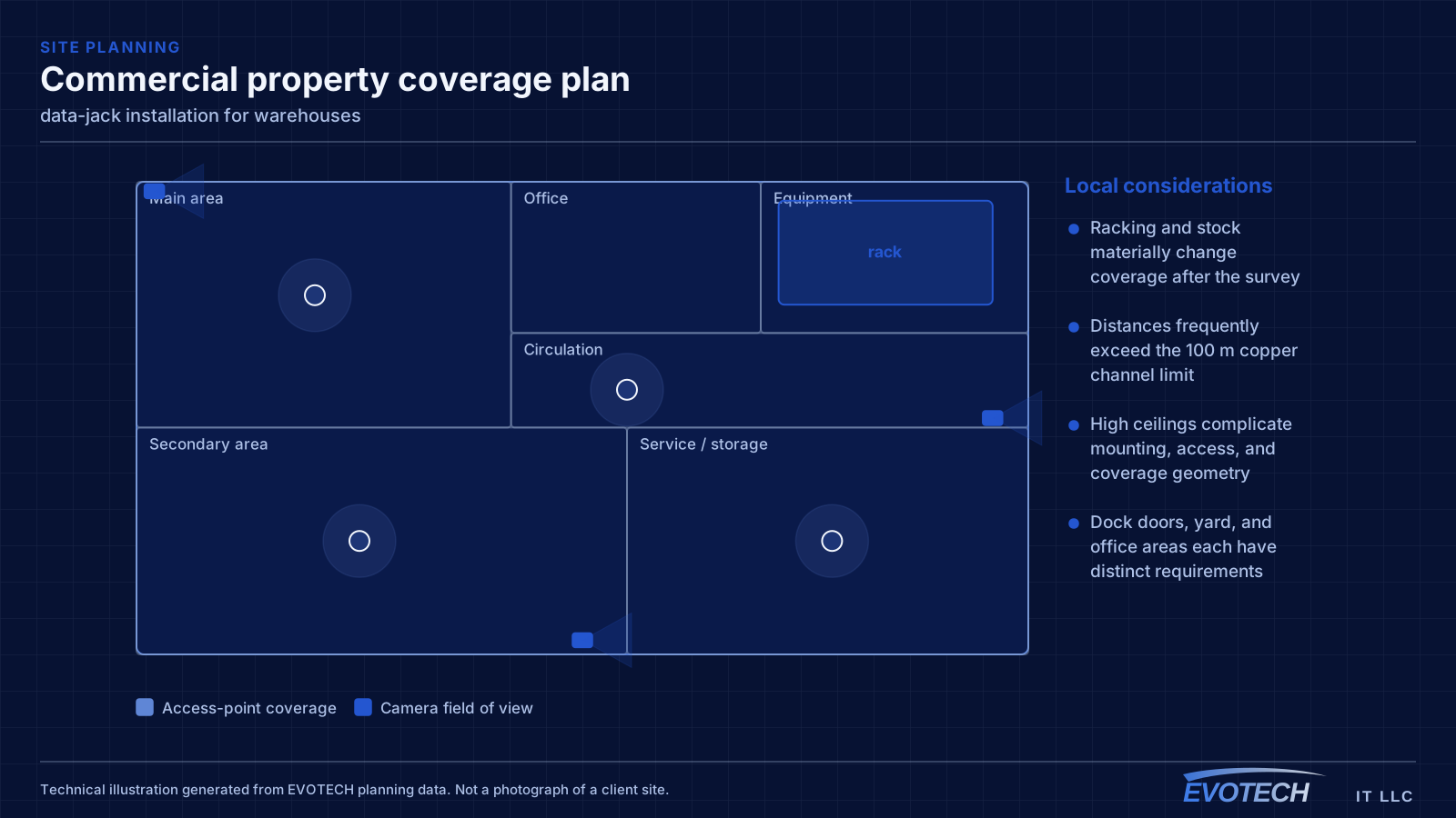
- Racking and stock materially change coverage after the survey
- Distances frequently exceed the 100 m copper channel limit
- High ceilings complicate mounting, access, and coverage geometry
- Dock doors, yard, and office areas each have distinct requirements
What data-jack installation usually involves
The dominant failure is untwist. Twisted-pair cable rejects noise because of the twist rate, and every centimetre of pair untwisted at the punch-down is a small crosstalk penalty. Combined across four pairs and two ends, sloppy terminations can move a link from comfortable margin to marginal.
The second failure is component mismatch. A jack rated one category below the cable caps the entire channel at the lower rating, and nothing about the installation looks wrong. The third is mechanical: a plate mounted without a low-voltage bracket, so the cable takes strain every time something is plugged in.
- Excess untwist at the punch-down degrading crosstalk performance
- Jacks rated below the cable capping the channel
- No low-voltage bracket, so the cable carries plug-in strain
- Insufficient service loop, leaving no material for re-termination
- Inconsistent wiring scheme between ends causing split pairs
Topology, mounting height, and roaming for handhelds
Where a building exceeds copper reach from a single position, the usual answer is one or more intermediate distribution points fed by fiber, each serving its area with copper within the limit. This is standard structured-cabling practice and it is far more reliable than attempting to stretch copper or bridge wirelessly across the building.
Access-point mounting height is a genuine design decision in high-ceiling spaces, not a default. Mounting at the roof deck maximises line of sight but puts the access point far from the devices and often above the racking, where the signal has to travel down through stock. Mounting lower — at or just above racking height, aimed along the aisles — frequently produces better coverage where the scanners actually are.
Roaming matters because the primary clients are mobile. A forklift-mounted or handheld scanner moving down an aisle needs clean handoffs between cells. That is a function of overlap and channel planning, and it is best validated by walking the aisles with the racking loaded.
- Fiber to intermediate distribution points where distance exceeds copper limits
- Mounting height chosen deliberately rather than defaulting to the roof deck
- Coverage designed along aisles, with directional antennas where useful
- Roaming validated by walking loaded aisles, not an empty floor
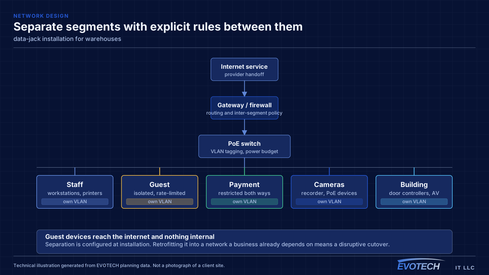
- Office, operations, and building-system traffic segmented
Why the outlet decides the channel
A certification test measures the complete path: patch cord, patch panel, horizontal cable, and outlet. Insertion loss and crosstalk contributions from the connectors are a meaningful share of the total budget, particularly at the higher frequencies where Cat6 and Cat6A links have the least margin. A well-made termination preserves margin; a poor one consumes it.
- Connector contribution is a significant part of the total loss and crosstalk budget
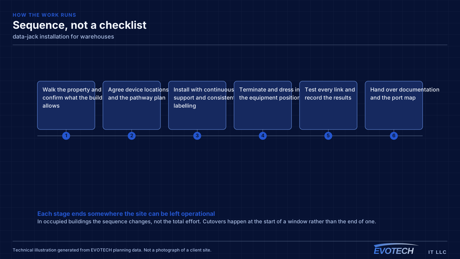
- T568A or T568B, applied consistently across every run in the building
- Service loop retained in the wall for future re-termination
- Low-voltage bracket or box to take mechanical strain off the cable
- Jack category matched to the cable and the patch panel
Frequently asked questions
What changes about data-jack installation in warehouses?
The operating environment does. Warehouses bring specific constraints — how the space is used, when work can happen, and what has to keep running — and those shape the data-jack installation plan as much as the service's own technical requirements.
Why did a link start failing after a jack was replaced?
Usually untwist or category mismatch. If more pair was untwisted at the punch-down than the standard allows, crosstalk performance drops, and a link that previously passed with small margin can fail. If the replacement jack is a lower category than the cable, the whole channel is capped at the lower rating. Both show up immediately in a certification test.
Why did warehouse Wi-Fi get worse after the racking was stocked?
Because the stock changed the radio environment. Metal racking reflects and palletised goods absorb, so coverage measured across an open floor no longer applies. This is why warehouse designs should assume loaded conditions and why validation should happen with the aisles full.