The short version
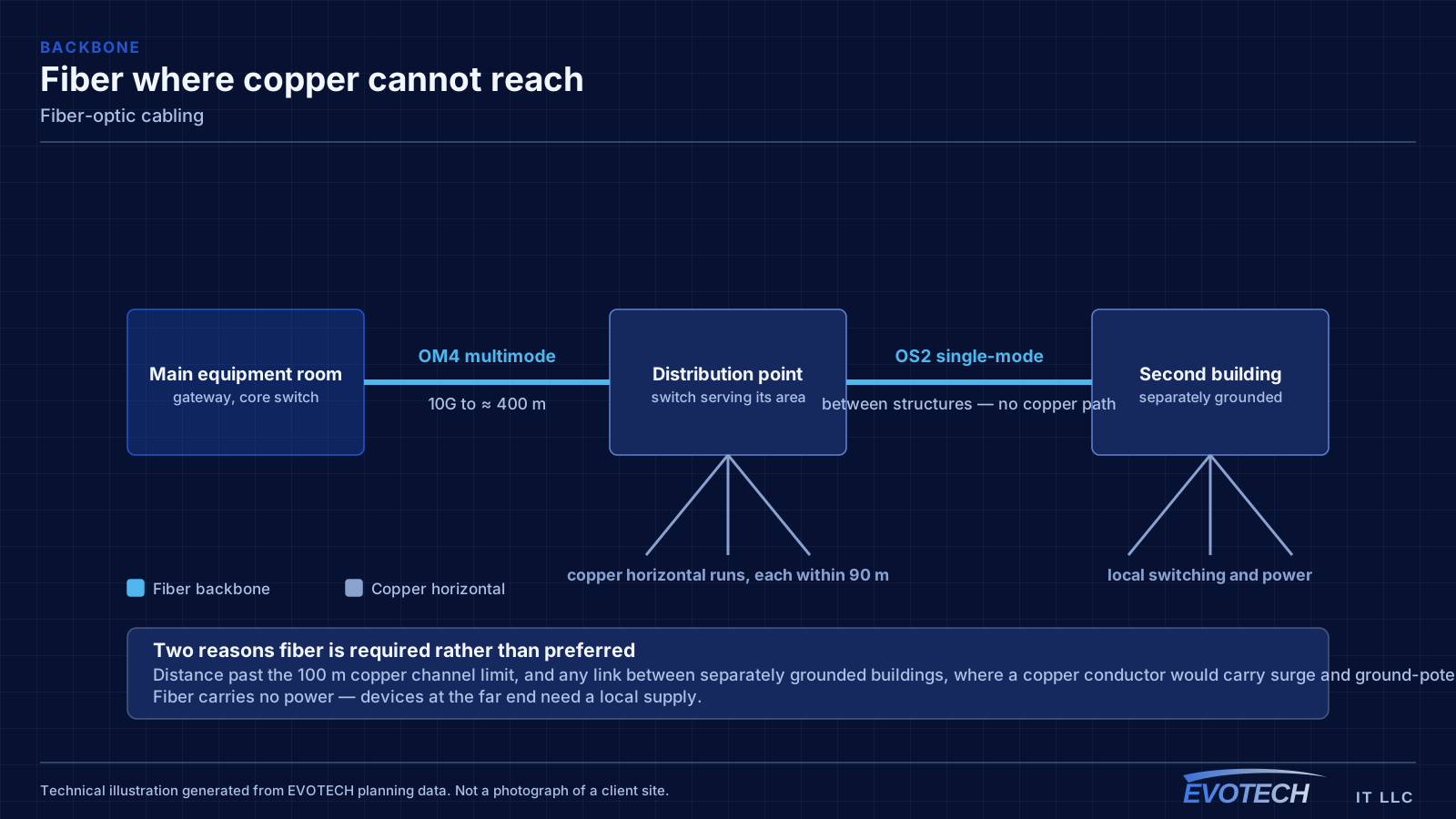
Fiber gets specified for reasons copper cannot address. The first is distance — multimode carries 10 gigabit a few hundred metres and single-mode carries it far further, while copper stops at 100 metres. The second is electrical isolation: a link between two separate buildings should not be a copper conductor, because the two structures can sit at different ground potentials and a lightning event has to go somewhere.
Inside a single building, fiber typically appears as a backbone between the main equipment room and intermediate closets, with copper handling the horizontal runs from those closets out to devices. That split is the standard structured-cabling shape and it exists because each medium is doing what it is good at.
Who this work is for
Fiber requests cluster around distance, separation, and capacity.
- Warehouses and large-footprint buildings where a single equipment room cannot reach every area within copper limits
- Campus and multi-building sites needing a link between structures
- Buildings with intermediate distribution closets requiring backbone uplinks
- Sites aggregating many cameras or access points into a core switch
- Detached outbuildings, shops, and guardhouses beyond copper distance
Fiber type, splice method, and the link budget
Multimode fiber — OM3 and OM4 in current installations — is the usual choice for in-building backbones. OM3 supports 10 gigabit to roughly 300 metres and OM4 to roughly 400 metres, which covers almost any single building. Single-mode fiber carries far greater distances and is the correct choice for building-to-building links and anything with a long horizon.
Terminations are either fusion splices or mechanical connections. A fusion splice welds the fiber cores together and produces very low loss; it needs a splicer and controlled conditions but gives the most consistent result. Mechanical connections are faster to deploy in the field and acceptable in many situations, with somewhat higher loss per connection. Which is appropriate depends on the link budget and how much margin the design has to spare.
That link budget is the arithmetic that governs the whole design: transmitter power, minus fiber attenuation over the distance, minus loss at each connector and splice, must leave enough at the receiver. Every connector pair spends part of the budget, which is why designs avoid unnecessary patch points on long links.
- OM3 to roughly 300 m and OM4 to roughly 400 m at 10 gigabit
- Single-mode for building-to-building and long-horizon links
- Fusion splicing for lowest and most consistent loss
- Every connector and splice consumes part of the link budget
- Transceiver type must match the fiber type at both ends
What tends to go wrong
Fiber problems are almost always contamination or handling. A connector end face with a single particle of dust on it can add loss well beyond the link budget, and the particle is invisible without a scope. Inspect-before-connect exists because the failure is so common and so easy to prevent.
The other failures are mechanical: a bend tighter than the cable's minimum radius causing macrobending loss, a pull that exceeded the cable's tension rating and stressed the fibers, and a mismatch between fiber types where a multimode patch cord ends up on a single-mode link.
- Contaminated connector end faces adding loss invisible to the naked eye
- Bend radius violations in enclosures, trays, and at wall entries
- Excess pulling tension damaging fibers inside an intact jacket
- Multimode and single-mode components mixed on one link
- Unprotected splice trays with no strain relief or slack storage
How the work runs
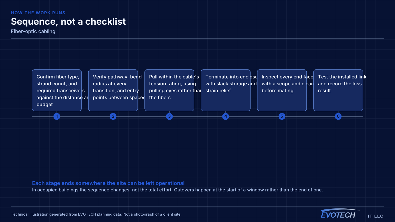
Fiber work is sequenced around protecting the glass: pull first, terminate in controlled conditions, test before anything goes live.
- Confirm fiber type, strand count, and required transceivers against the distance and budget
- Verify pathway, bend radius at every transition, and entry points between spaces
- Pull within the cable's tension rating, using pulling eyes rather than the fibers
- Terminate into enclosures with slack storage and strain relief
- Inspect every end face with a scope and clean before mating
- Test the installed link and record the loss result
- Label both ends, document strand assignments, and cap unused connectors
Testing and verification
The baseline test is an insertion-loss measurement across the installed link, compared against the calculated budget for that distance and connector count. A link that passes with margin is a link that will tolerate a future re-patch.
Where a project needs to characterise the link in detail — locating a specific high-loss event, documenting a long outdoor run, or resolving a dispute — a trace-based measurement identifies where along the fiber the loss occurs rather than just reporting the total.
- End-face inspection with a scope before every mating
- Insertion-loss testing against the calculated link budget
- Trace-based analysis where individual events need locating
- Bidirectional testing where the specification requires it
- Results recorded per strand with the as-built documentation
What changes the scope
Fiber scope varies mostly with route difficulty and strand count.
- Distance and whether the route is indoor, outdoor, or both
- Fiber type and strand count, including spares
- Termination method and connector count
- Enclosure and splice-tray hardware at each end
- Outdoor path construction: aerial, direct burial, or in conduit
- Transceiver selection at each switch
- Testing depth requested, from loss testing to trace analysis
What drives the cost
Fiber cost concentrates in the route and the terminations rather than the cable itself.
- Route length and construction method, especially for outdoor segments
- Strand count and whether spares are included
- Number of terminations and the method used
- Enclosures, trays, and protection hardware
- Transceivers at each end
- Testing and documentation depth
- Trenching, boring, or aerial work on between-building routes
Common mistakes
Fiber punishes shortcuts more visibly than copper does.
- Mating connectors without inspecting and cleaning end faces
- Installing exactly the strand count needed with no spares
- Violating bend radius inside enclosures where slack is coiled
- Pulling on the fibers rather than the cable's strength member
- Running copper between separate buildings to save on fiber
- Leaving unused connectors uncapped in a dusty environment
Honest limitations
These are the boundaries of what this service can do, stated up front rather than discovered later.
- Fiber carries no power. Devices at the far end need a local power source or a copper leg from a nearby powered position.
- Outdoor routes may involve trenching, boring, or aerial work and any permissions those require.
- Damaged fiber is repaired by splicing rather than re-terminating in place; slack storage exists to make that possible.
- Link performance is bounded by the calculated budget; adding patch points consumes margin.
Popular services nearby
Frequently searched near this area — the pages people look for most.
Frequently asked questions
When is fiber necessary rather than optional?
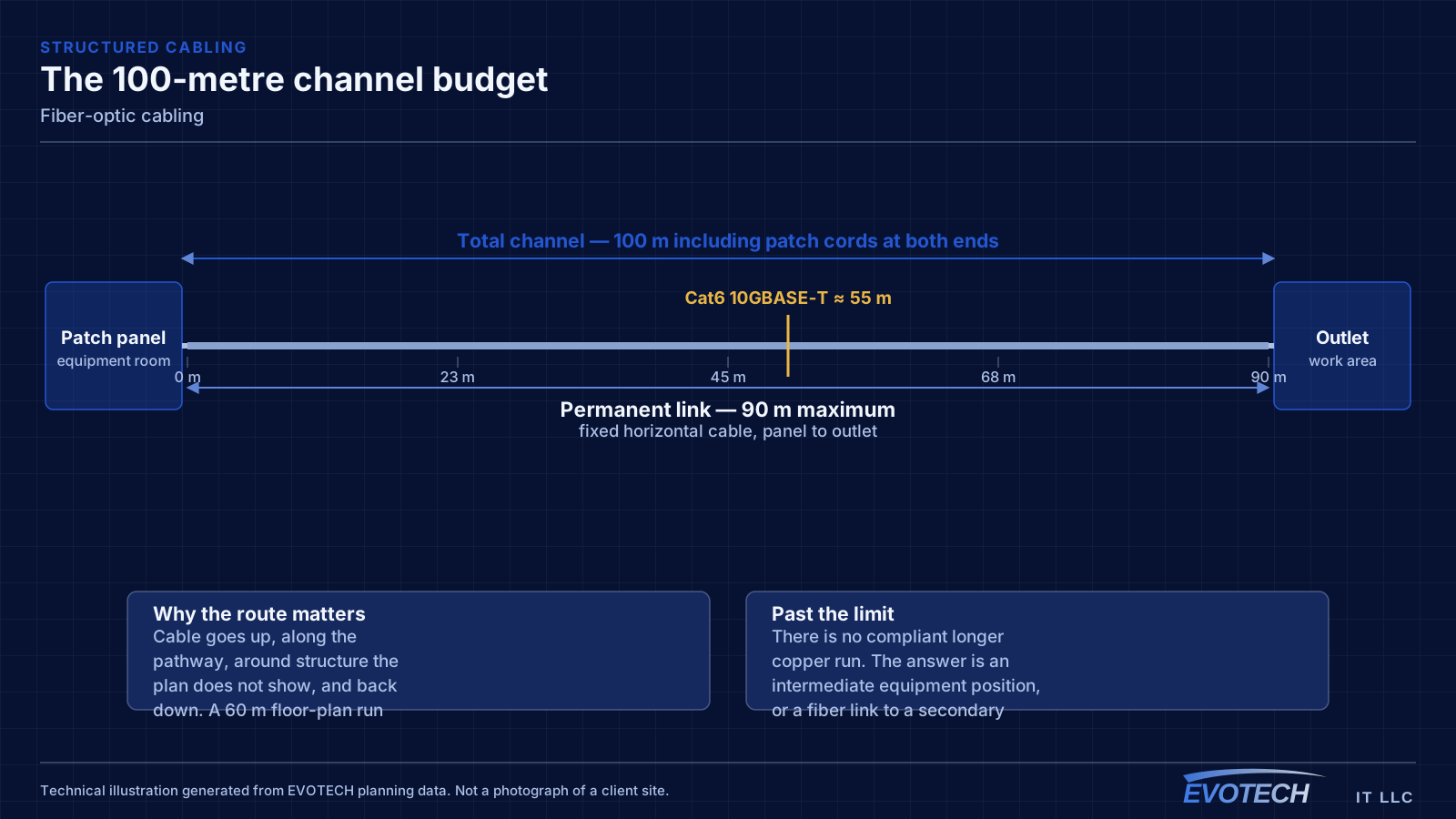
Two situations make it necessary rather than a preference. First, distance: past the 100-metre copper channel limit there is no compliant copper answer. Second, links between separate buildings, where a copper conductor creates a path for surge and ground-potential differences. Inside those two cases fiber is not an upgrade — it is the correct method.
Multimode or single-mode?
Multimode — OM3 or OM4 — is the usual choice for backbones inside a single building, where its few-hundred-metre reach at 10 gigabit is more than sufficient and the optics cost less. Single-mode is the choice between buildings, on long campus routes, and anywhere the link has a long horizon and might need to carry more later.
Is fusion splicing always better than mechanical termination?
It produces lower and more consistent loss, which matters when the link budget is tight or the run is long. Mechanical terminations are quicker in the field and perfectly serviceable on short links with generous margin. The decision comes out of the budget calculation rather than preference.
Why do fiber links need cleaning if the connectors look clean?
Because the core is smaller than a particle of dust. Contamination sufficient to fail a link is invisible without a scope, and mating a dirty connector can transfer the contamination — and sometimes damage the mating end face permanently. Inspect-and-clean before every connection is the standard practice for exactly this reason.