The short answer
Install more ports than you have cables. A patch panel is cheap relative to the labour of installing it, and a panel with spare positions accepts the next run without a new panel, a new mounting position, and a re-dress of everything around it.
Then label it properly, using a scheme decided before the first cable is pulled. The single biggest determinant of how long a future change takes is whether someone can look at a port and know where it goes without tracing anything.
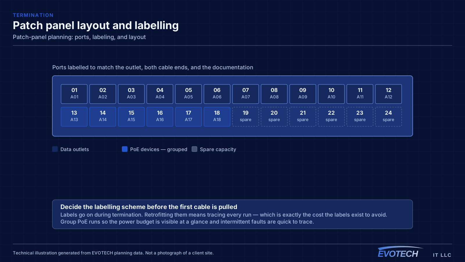
How many ports to install
Count the runs, then round up substantially. A 24-port panel for 18 runs leaves six positions, which sounds adequate and typically is not — the next phase of work adds cameras, access points, or a door controller, and those runs need somewhere to land.
Panels come in common port counts and the price difference between them is modest. Installing a 48-port panel for 30 runs costs a little more now and avoids adding a second panel later, which involves finding rack space, re-dressing cable, and updating documentation that was correct until that moment.
The exception is where rack space is genuinely tight, in which case the tradeoff is explicit rather than accidental — and it is a signal that the rack was sized too small rather than that the panel is too big.
- Count runs, then round up rather than fitting exactly
- Anticipate the next phase: cameras, access points, door controllers
- Panel price difference is small relative to installation labour
- Adding a second panel later means re-dressing and re-documenting
- A panel that will not fit is a sign the rack was undersized
Panel layout and rack position
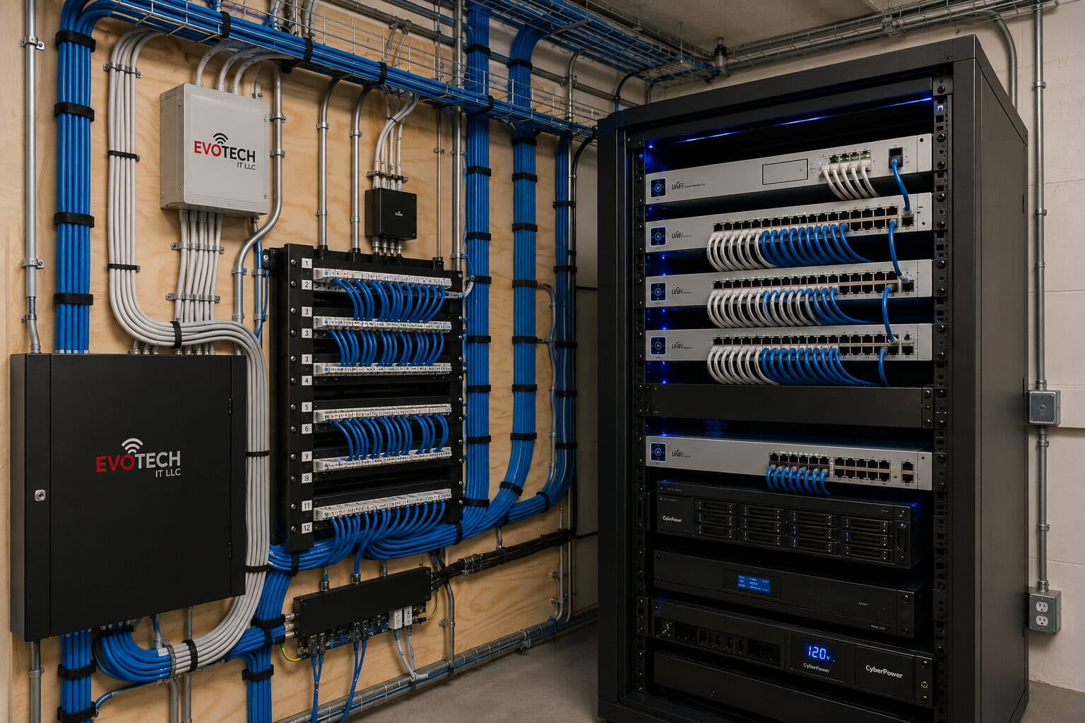
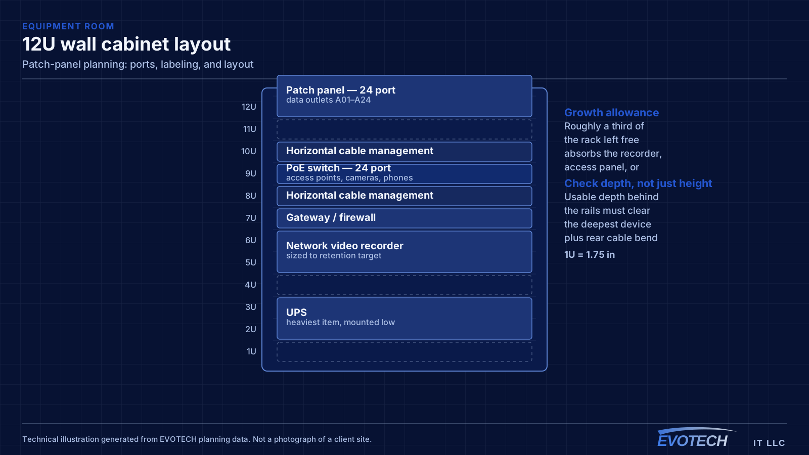
Patch panels belong grouped, with cable management immediately below or above each group and the switching positioned so patch cords have a short, direct path. The common failure is panels at the top of a rack and switches at the bottom, which produces long cords running the height of the cabinet and a face nobody can work behind.
Where there are multiple panels, grouping them by area or by system makes patching intuitive. One panel for the north side of the floor and one for the south, or one for data outlets and one for cameras, means a technician can find the right region before reading a single label.
Leave a rack unit of horizontal management between each panel and the switch it feeds. It costs space and it is what keeps the cords dressed rather than woven.
- Panels grouped, with switching positioned for short patch runs
- Horizontal management between each panel and its switch
- Multiple panels grouped by area or by system
- Avoid panels and switches at opposite ends of the rack
- Leave room to work at the rack face
The labeling scheme, decided before the first pull
A labeling scheme has to be decided before cable is pulled, because labels get applied during termination and retrofitting them means tracing every run — which is exactly the cost the labels exist to avoid.
A workable scheme identifies the location unambiguously: a room or grid reference plus a sequence number, applied identically at the outlet, on the cable at both ends, and on the patch panel port. The specific convention matters far less than using one consistently and writing it down.
The test of a scheme is whether someone unfamiliar with the building can find the outlet corresponding to a panel port without help. If they need to ask, the scheme is not doing its job.
- Decide the scheme before pulling cable, not after
- Label the outlet, both cable ends, and the panel port identically
- Use location plus sequence rather than arbitrary numbering
- Document the scheme itself, not just the labels
- Test: can a stranger find the outlet from the port label?
Termination quality at the panel
The panel is one of two termination points in every channel, and its contribution to insertion loss and crosstalk is a meaningful share of the total budget. Excess untwist at the punch-down consumes margin at exactly the frequencies where the least is available.
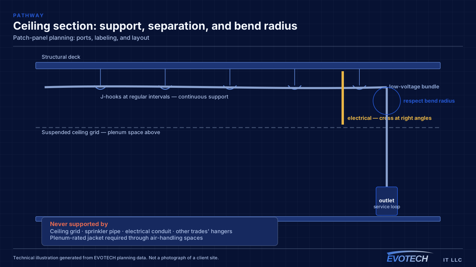
The mechanical side matters too. Cable should be supported and strain-relieved at the panel so that patching does not put tension on the terminations, and there should be enough service loop that a port can be re-terminated once without pulling cable from the ceiling.
Panel category has to match the cable and the outlets. A Cat6A run terminated on a Cat6 panel is a Cat6 channel, and certification testing will report it as one regardless of what was purchased.
- Minimal untwist at every punch-down
- Cable supported and strain-relieved at the panel
- Service loop retained for future re-termination
- Panel category matched to cable and outlets
- Terminations tested rather than assumed correct
Patch cords, colour, and the documentation that survives
Patch cords should be the right length. A rack full of two-metre cords where thirty centimetres would do is the single most common cause of an unmanageable rack face, and it makes tracing a specific cord genuinely difficult.
Colour coding by function — data, cameras, access control, uplinks — is a small habit with a large payoff, particularly for whoever works on the rack next. It costs nothing beyond buying cords in a few colours and being consistent about which is which.
Finally, the documentation. A port-to-location map, stored somewhere it will still be found in three years, is what turns a rack from a working installation into a maintainable one. Photographs of the finished rack face are a useful supplement, because they record the intended arrangement before entropy sets in.
- Patch cords sized to the actual distance, not a standard length
- Colour coding by function, applied consistently
- Port-to-location map kept somewhere retrievable
- Photograph the finished rack face as a reference
- Update documentation when changes are made, or it becomes misleading
Panels feeding PoE devices need a little extra thought
A patch panel carrying cameras, access points, and door hardware is doing something a data-only panel is not: passing current continuously through dozens of terminations. That has two practical consequences worth planning for.
The first is heat. A dense block of PoE runs terminated together warms up, and the terminations at the centre of that block run warmest. Spacing PoE groups rather than packing them, and giving the rack a genuine airflow path, matters more here than on a panel carrying only data.
The second is traceability under load. When a camera drops, the useful diagnostic is knowing which switch port feeds it and what that port's power draw and error counters look like. That is trivial when the panel is labeled and the port-to-camera mapping is documented, and genuinely tedious when it is not — and PoE devices fail intermittently far more often than desk outlets do, so the mapping gets used.
For that reason, grouping PoE runs onto their own panel or a clearly delineated section is worth doing even in a small installation. It makes the power budget visible at a glance and it makes the tracing straightforward when something misbehaves after dark.
- PoE terminations pass current continuously and generate heat
- Space PoE groups rather than packing them densely
- Group PoE runs onto their own panel or a clear section
- Document the port-to-device mapping; intermittent PoE faults make it necessary
- Label which ports carry power so the budget is visible at the rack
Frequently asked questions
How many spare ports should a patch panel have?
Enough to absorb the next phase of work — commonly a quarter to a third of the panel. The specific trigger is that adding a second panel later requires rack space, re-dressing, and documentation updates, all of which cost far more than the price difference between panel sizes at purchase.
Does the labeling convention matter, or just the consistency?
Consistency matters far more. Any scheme that unambiguously identifies a location works, provided it is applied at the outlet, both cable ends, and the panel port, and provided the scheme itself is written down. What fails is a scheme that only made sense to the person who installed it.
Should cameras and data share a patch panel?
They can, and separating them onto different panels — or clearly delineated sections — makes patching more intuitive and makes it obvious which ports carry PoE load. In racks with several systems, grouping by system is usually easier to work with than a single continuous numbering.
Is a punch-down panel better than a keystone panel?
Both work. Punch-down panels are quicker to terminate in volume and keep the assembly consistent; keystone panels allow mixed connector types and individual port replacement without disturbing neighbours. For a straightforward data installation the punch-down panel is usually the more efficient choice.
How do you label a panel when the building has no room numbering?
Invent a scheme and record it. A simple grid — a letter for the zone and a number for the position within it — works well in open-plan space where there are no room names to reference. What matters is that the same reference appears on the outlet, on both cable ends, and on the panel port, and that the scheme itself is written into the documentation so the next person can decode it without guessing.