Why this page exists
PoE camera installation for warehouses is shaped by how the space is used, not just by the service itself. Warehouses bring their own operating constraints, and this page pairs what poe camera installation actually involves with what that environment changes about it.
A PoE camera takes its power from the same Ethernet cable that carries its video, which removes the need for a local outlet at every mounting position. That is the entire practical appeal: one run per camera, no electrician at each soffit, and centralised power that can sit behind a UPS so the cameras stay up during a short outage.
The building changes its own radio environment
A warehouse surveyed empty and a warehouse full of stock are different radio environments. Metal racking reflects, palletised inventory absorbs, and coverage that measured well across an open floor can disappear once the aisles fill. Any design based on an empty-building survey should be treated as provisional.
The second defining feature is distance. Warehouse footprints regularly exceed what a single equipment room can serve within the 100-metre copper limit, which means either intermediate equipment positions connected by fiber or a deliberately distributed design.
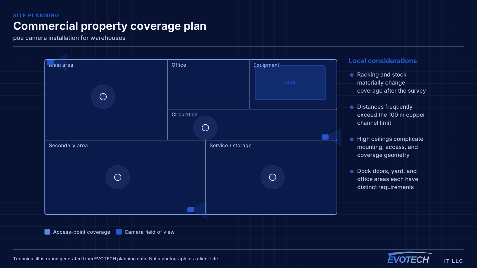
- Racking and stock materially change coverage after the survey
- Distances frequently exceed the 100 m copper channel limit
- High ceilings complicate mounting, access, and coverage geometry
- Dock doors, yard, and office areas each have distinct requirements
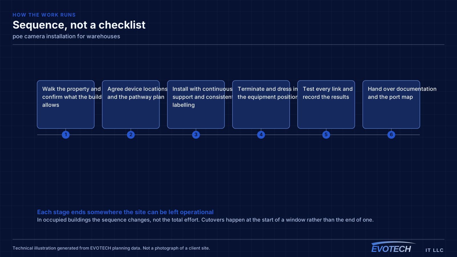
What poe camera installation usually involves
The characteristic PoE problem is a camera that reboots under specific conditions — usually at night when its infrared illuminator switches on and its draw rises. If the switch is near its budget, the additional load pushes it over and devices drop. Because it happens after dark, it often gets reported as an intermittent network fault.
The second problem is distance. PoE inherits the same 100-metre channel limit as any Ethernet run, and voltage drop over long runs on thin conductors reduces the power actually reaching the camera. A run that works at 60 metres may be marginal at 95 with a high-draw device on the end.
- Switch PoE budget exceeded once illuminators or heaters engage at night
- Long runs delivering less power at the camera than the switch reports sending
- Higher-draw devices such as PTZ cameras and heated housings mis-budgeted
- Thin or copper-clad-aluminium cable increasing resistance and voltage drop
- Dense PoE bundles heating and raising insertion loss
- No UPS on the switch, so cameras drop with any brief power interruption
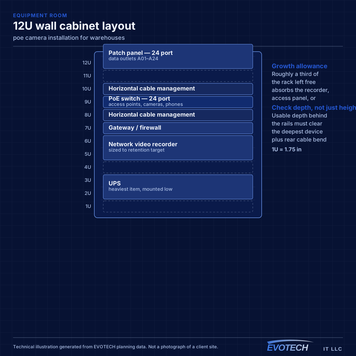
Topology, mounting height, and roaming for handhelds
Where a building exceeds copper reach from a single position, the usual answer is one or more intermediate distribution points fed by fiber, each serving its area with copper within the limit. This is standard structured-cabling practice and it is far more reliable than attempting to stretch copper or bridge wirelessly across the building.
Access-point mounting height is a genuine design decision in high-ceiling spaces, not a default. Mounting at the roof deck maximises line of sight but puts the access point far from the devices and often above the racking, where the signal has to travel down through stock. Mounting lower — at or just above racking height, aimed along the aisles — frequently produces better coverage where the scanners actually are.
Roaming matters because the primary clients are mobile. A forklift-mounted or handheld scanner moving down an aisle needs clean handoffs between cells. That is a function of overlap and channel planning, and it is best validated by walking the aisles with the racking loaded.
- Fiber to intermediate distribution points where distance exceeds copper limits
- Mounting height chosen deliberately rather than defaulting to the roof deck
- Coverage designed along aisles, with directional antennas where useful
- Roaming validated by walking loaded aisles, not an empty floor
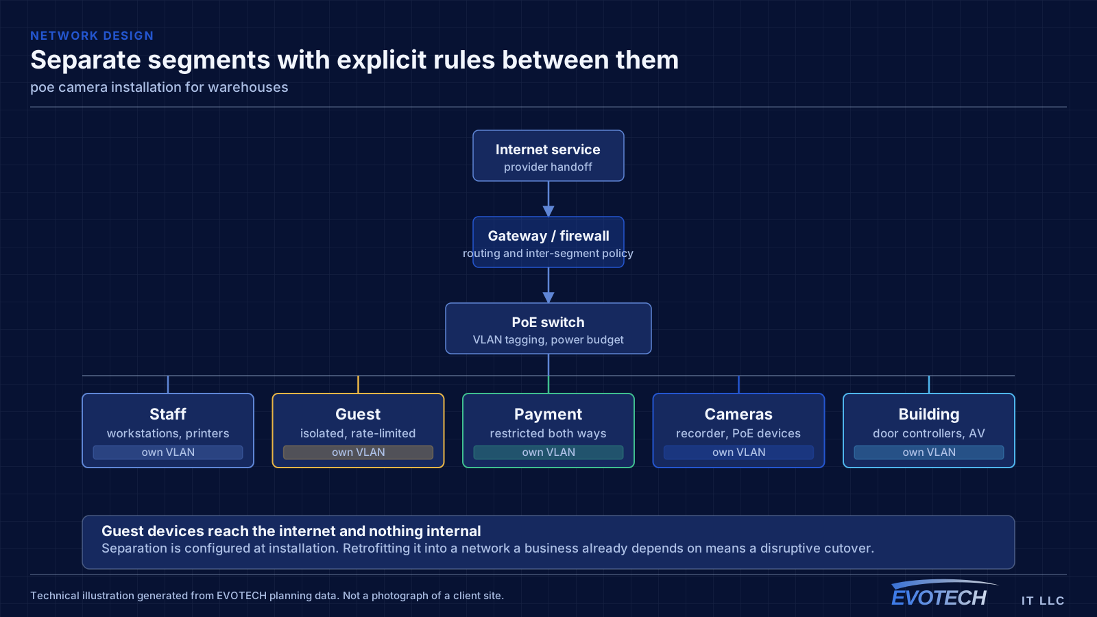
- Office, operations, and building-system traffic segmented
PoE classes, budget arithmetic, and distance
The standards define escalating power classes. Type 1 (802.3af) supplies up to about 15.4 W at the switch with roughly 12.95 W available at the device. Type 2 (802.3at) raises that to about 30 W supplied and 25.5 W available. Type 3 and Type 4 under 802.3bt reach roughly 60 W and 90 W supplied, with about 51 W and 71 W available respectively. The gap between supplied and available is the loss in the cable, and it grows with length and with thinner conductors.
- 802.3af up to ~15.4 W supplied; 802.3at up to ~30 W; 802.3bt to ~60 W and ~90 W
- Budget on peak draw with illuminators, heaters, and motors engaged
- Same 100 m channel limit as any Ethernet run
- Full-copper conductors of correct gauge; avoid copper-clad aluminium on PoE runs
- Keep PoE bundles loose enough to shed heat
- Put the switch on a UPS so cameras survive short outages
Frequently asked questions
What changes about poe camera installation in warehouses?
The operating environment does. Warehouses bring specific constraints — how the space is used, when work can happen, and what has to keep running — and those shape the poe camera installation plan as much as the service's own technical requirements.
Why do cameras reboot at night but work fine during the day?
Almost always PoE budget. Infrared illuminators engage after dark and the total draw rises, pushing the switch past its budget. It presents as intermittent camera dropouts and gets misdiagnosed as a network fault. The fix is a switch with sufficient budget and headroom, calculated from peak draw rather than idle.
Why did warehouse Wi-Fi get worse after the racking was stocked?
Because the stock changed the radio environment. Metal racking reflects and palletised goods absorb, so coverage measured across an open floor no longer applies. This is why warehouse designs should assume loaded conditions and why validation should happen with the aisles full.