Why this page exists
PoE camera installation for schools and educational facilities is shaped by how the space is used, not just by the service itself. Schools and educational facilities bring their own operating constraints, and this page pairs what poe camera installation actually involves with what that environment changes about it.
A PoE camera takes its power from the same Ethernet cable that carries its video, which removes the need for a local outlet at every mounting position. That is the entire practical appeal: one run per camera, no electrician at each soffit, and centralised power that can sit behind a UPS so the cameras stay up during a short outage.
Density in bursts, across a campus
A classroom with thirty students on devices is one of the densest wireless environments in any building type, and it happens simultaneously in every classroom on a bell schedule. That is a capacity problem of a specific shape: predictable, synchronised, and concentrated.
The campus dimension compounds it. Multiple buildings, outdoor circulation, portable classrooms, gymnasiums, and administrative areas each need coverage, and the distances involved usually exceed what copper alone can serve from one position.
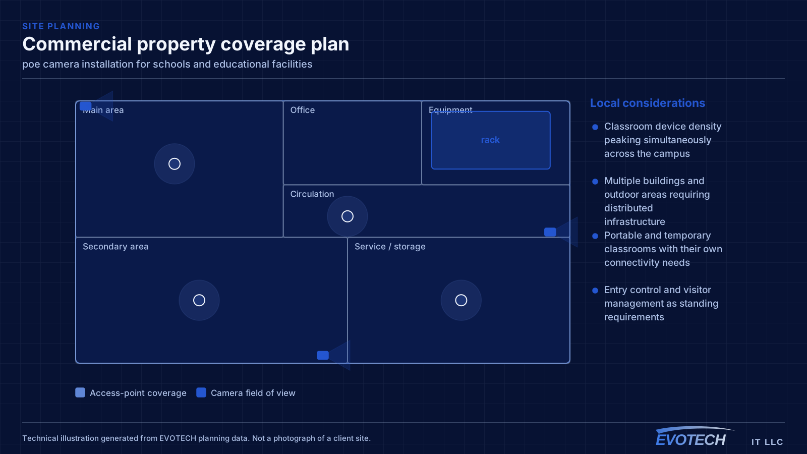
- Classroom device density peaking simultaneously across the campus
- Multiple buildings and outdoor areas requiring distributed infrastructure
- Portable and temporary classrooms with their own connectivity needs
- Entry control and visitor management as standing requirements
What poe camera installation usually involves
The characteristic PoE problem is a camera that reboots under specific conditions — usually at night when its infrared illuminator switches on and its draw rises. If the switch is near its budget, the additional load pushes it over and devices drop. Because it happens after dark, it often gets reported as an intermittent network fault.
The second problem is distance. PoE inherits the same 100-metre channel limit as any Ethernet run, and voltage drop over long runs on thin conductors reduces the power actually reaching the camera. A run that works at 60 metres may be marginal at 95 with a high-draw device on the end.
- Switch PoE budget exceeded once illuminators or heaters engage at night
- Long runs delivering less power at the camera than the switch reports sending
- Higher-draw devices such as PTZ cameras and heated housings mis-budgeted
- Thin or copper-clad-aluminium cable increasing resistance and voltage drop
- Dense PoE bundles heating and raising insertion loss
- No UPS on the switch, so cameras drop with any brief power interruption
Classroom capacity and campus topology
Classroom wireless is a capacity design. A single access point serving a full class of devices needs adequate spectrum, and neighbouring classrooms on the same channel will contend with each other through the wall. That makes the channel plan across a corridor of classrooms as important as the access-point count — a plan that ignores the neighbours produces a corridor where every room is slow.
Campus topology follows standard structured-cabling practice at a larger scale: a main equipment position, fiber to distribution points in each building or wing, and copper from those points out to classrooms within the distance limit. Between-building links are fiber for both distance and electrical isolation.
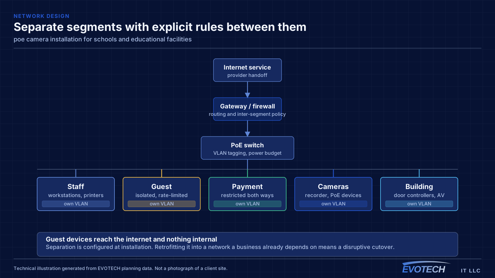
Segmentation separates student devices, staff devices, administrative systems, and building systems such as cameras and door controllers. Student access is typically the most restricted and the most heavily used, and separating it means student traffic cannot affect administrative systems.
- Capacity designed per classroom with a corridor-wide channel plan
- Fiber backbone between buildings and to per-building distribution
- Student, staff, administrative, and building-system segments
- Coverage for gymnasiums, libraries, cafeterias, and outdoor areas
- Portable classroom connectivity planned rather than improvised
PoE classes, budget arithmetic, and distance
The standards define escalating power classes. Type 1 (802.3af) supplies up to about 15.4 W at the switch with roughly 12.95 W available at the device. Type 2 (802.3at) raises that to about 30 W supplied and 25.5 W available. Type 3 and Type 4 under 802.3bt reach roughly 60 W and 90 W supplied, with about 51 W and 71 W available respectively. The gap between supplied and available is the loss in the cable, and it grows with length and with thinner conductors.
- 802.3af up to ~15.4 W supplied; 802.3at up to ~30 W; 802.3bt to ~60 W and ~90 W
- Budget on peak draw with illuminators, heaters, and motors engaged
- Same 100 m channel limit as any Ethernet run
- Full-copper conductors of correct gauge; avoid copper-clad aluminium on PoE runs
- Keep PoE bundles loose enough to shed heat
- Put the switch on a UPS so cameras survive short outages
Frequently asked questions
What changes about poe camera installation in schools and educational facilities?
The operating environment does. Schools and educational facilities bring specific constraints — how the space is used, when work can happen, and what has to keep running — and those shape the poe camera installation plan as much as the service's own technical requirements.
Why do cameras reboot at night but work fine during the day?
Almost always PoE budget. Infrared illuminators engage after dark and the total draw rises, pushing the switch past its budget. It presents as intermittent camera dropouts and gets misdiagnosed as a network fault. The fix is a switch with sufficient budget and headroom, calculated from peak draw rather than idle.
How many access points does a classroom need?
It is a capacity question rather than a coverage one. A classroom with a full class on devices concentrates demand into one cell, and neighbouring classrooms on the same channel contend through the wall. That usually means one access point per classroom with a corridor-wide channel plan, rather than fewer access points at higher power.