
The short answer
The difference between T568A and T568B is only which two pairs swap position: the orange and green pairs trade places. Everything else stays identical. T568B, the more common choice in North American commercial work, runs pin 1 white/orange, pin 2 orange, pin 3 white/green, pin 4 blue, pin 5 white/blue, pin 6 green, pin 7 white/brown, pin 8 brown. T568A runs pin 1 white/green, pin 2 green, pin 3 white/orange, pin 4 blue, pin 5 white/blue, pin 6 orange, pin 7 white/brown, pin 8 brown. Both terminate all four pairs; both are valid under ANSI/TIA-568. What matters is consistency: terminate both ends of a run to the same standard and you get a straight-through cable that works for Ethernet.
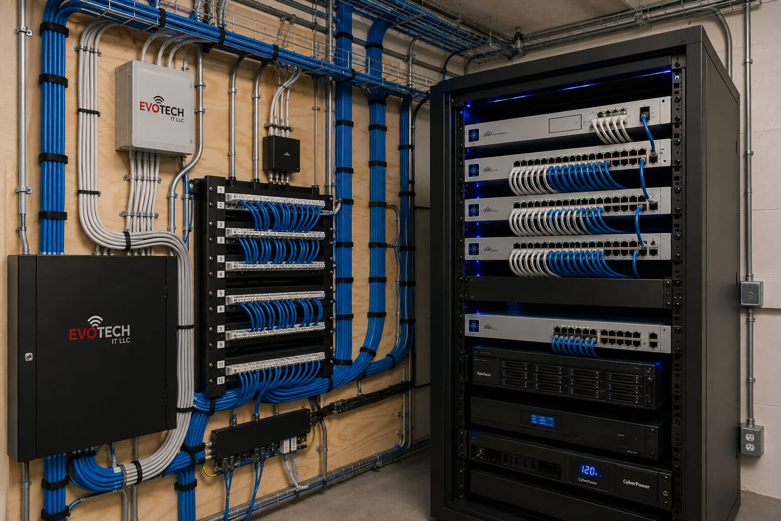
Structured cabling is the whole discipline the pinout lives inside. ANSI/TIA-568 organizes a building's telecommunications wiring into six subsystems and sets a hard distance rule: the permanent horizontal run from the telecom room to the work area outlet may not exceed 90 meters (295 ft), and patch or equipment cords add up to no more than 10 meters, for a total channel of 100 meters (328 ft). Pair a matched pinout, that distance budget, and TIA-606 labeling with tested Category 5e, 6, or 6A cable and you have a plant that supports 1000BASE-T or 10GBASE-T within spec. The sections below give the full reference tables, the physics behind the pair assignments, and the practical rules for choosing A versus B and straight-through versus crossover.
T568A or T568B: which to pick, and when each cable type applies
Pick one standard and use it everywhere in a given site. T568A and T568B are electrically identical because both keep the same four pairs on the same pin-pair groupings; only the orange and green pairs swap which pins they occupy. A cable is straight-through when both ends use the same standard (A-to-A or B-to-B), and that is what over 99% of modern installations need. Gigabit and faster Ethernet use all four pairs bidirectionally, and Auto-MDI/MDIX on virtually every switch and NIC made since roughly 2000 electronically flips transmit and receive as needed, so a straight-through cable connects a PC to a switch or a switch to a switch without a crossover.
T568B dominates North American commercial and residential structured cabling; many enterprise standards and installers default to it. T568A is required by the U.S. federal residential wiring guidance (the former TIA-570 residential recommendation) and is common in government and some international work because it maintains backward compatibility with older USOC one- and two-pair voice wiring on pins 4-5 and 3-6. Neither is technically superior for data. The failure mode to avoid is mixing standards accidentally on the two ends of a single run, which produces an unintended crossover.
A crossover cable deliberately terminates one end T568A and the other T568B, swapping the transmit and receive pairs so two like devices could talk before Auto-MDIX existed. Today crossovers are largely obsolete for host-to-host links but still appear in legacy gear, some industrial equipment, and certain uplink scenarios without auto-negotiation. When in doubt, build straight-through B-to-B and let Auto-MDIX handle direction.
- T568A pin order (1-8): white/green, green, white/orange, blue, white/blue, orange, white/brown, brown.
- T568B pin order (1-8): white/orange, orange, white/green, blue, white/blue, green, white/brown, brown.
- A vs B differ only by swapping the orange pair (pins 1-2 / 3-6 region) with the green pair; all other pins are identical.
- Straight-through = same standard both ends (A-A or B-B); this is the default for PC-to-switch and modern switch-to-switch.
- Crossover = A on one end, B on the other; needed only for legacy non-Auto-MDIX device-to-like-device links.
- Choose B for typical U.S. commercial jobs, A where federal residential or legacy USOC voice compatibility is specified; then stay consistent site-wide.
The exact pin-to-pair color map: four pairs, eight conductors
A four-pair balanced twisted-pair cable carries four color-coded pairs: blue, orange, green, and brown. Each pair has one solid-color conductor and one conductor that is white with a stripe (or ring) of the pair color, commonly written as white/blue, white/orange, and so on. The RJ45 (technically an 8P8C) modular connector has eight pins, numbered 1-8 left to right when you hold the plug with the gold contacts facing you and the locking tab pointing down and away.
The two standards assign pairs to pin positions differently, but both preserve the electrical grouping that Ethernet requires. In both T568A and T568B, the blue pair always sits on pins 4 and 5 (the center position, historically the analog voice line 1), and the brown pair always sits on pins 7 and 8. The orange and green pairs occupy pins 1-2 and 3-6; T568A puts green on 1-2 and orange on 3-6, while T568B puts orange on 1-2 and green on 3-6. Note that one Ethernet signal pair straddles the split positions 3 and 6, which is why maintaining the correct pair twist to those two pins matters for crosstalk performance.
The critical wiring discipline is that pins 3 and 6 must belong to the same physical twisted pair. A common miswire, splitting pins 3 and 6 across two different pairs, produces a cable that may pass 10/100 Ethernet but fails gigabit and generates severe near-end crosstalk. Always follow the standard's pair grouping exactly.
- Four pairs by color: Pair 1 = blue / white-blue; Pair 2 = orange / white-orange; Pair 3 = green / white-green; Pair 4 = brown / white-brown.
- Pins are numbered 1-8 on the 8P8C (RJ45) connector, contacts facing you, tab down.
- Blue pair is on pins 4-5 in BOTH standards (center pins, legacy voice line 1).
- Brown pair is on pins 7-8 in BOTH standards.
- T568A: green pair on pins 1-2, orange pair on pins 3-6. T568B: orange pair on pins 1-2, green pair on pins 3-6.
- Pins 3 and 6 must be the same twisted pair; splitting them across pairs causes crosstalk and gigabit failure even if a link comes up.
The six structured-cabling subsystems of ANSI/TIA-568
ANSI/TIA-568 (the current structured cabling family, formerly organized as 568-C and reissued as the 568.0/568.1/568.2 documents) divides a building's telecommunications infrastructure into defined subsystems so that any authorized designer can lay out, install, and document a plant consistently. Working from the outside in, the entrance facility is where outside-plant and service-provider cabling enters the building and meets the intra-building wiring, including the demarcation point and network interface. The equipment room is a centralized space, more environmentally controlled than a closet, housing major distribution gear and servers that serve the whole building or campus.
Backbone cabling (also called vertical cabling) interconnects the entrance facility, equipment room, and the telecommunications rooms, running riser-to-riser between floors and building-to-building. It carries the aggregated traffic between distribution points and often uses fiber for the longer or higher-bandwidth links. The telecommunications room (or telecom enclosure) on each floor houses the horizontal cross-connect: patch panels, switches, and the transition from backbone to horizontal.
Horizontal cabling is the run from the telecom room out to each individual work-area outlet, and it is where the 90-meter permanent-link limit applies. The work area is the final subsystem: the outlet, faceplate, jack, and the patch cord to the end device, phone, computer, access point, or camera. Together these six subsystems form the complete path from carrier demarc to desktop.
- Entrance facility: point where outside/service-provider cabling enters the building; contains demarcation point and protection.
- Equipment room: centralized, environmentally controlled space for building- or campus-serving equipment and main cross-connects.
- Backbone (vertical) cabling: interconnects entrance facility, equipment room, and telecom rooms; frequently fiber for distance/bandwidth.
- Telecommunications room: per-floor space housing the horizontal cross-connect (patch panels, switches).
- Horizontal cabling: telecom room to the work-area outlet; subject to the 90 m permanent-link limit.
- Work area: the outlet, jack, faceplate, and patch cord to the end device (PC, phone, WAP, camera).
The 90 m + 10 m = 100 m channel model and category cable specs
ANSI/TIA-568 defines a balanced twisted-pair channel with a firm length budget. The permanent link, the fixed in-wall horizontal run from the patch panel in the telecom room to the outlet in the work area, is limited to 90 meters (295 feet). On top of that, the standard allocates up to 10 meters (33 feet) total for the flexible cords: the patch cord at the telecom-room end and the equipment/work-area cord at both ends combined. The sum is the 100-meter (328-foot) channel, the maximum end-to-end distance for which the electrical performance of Category 5e, 6, and 6A is guaranteed.
These lengths are not arbitrary. They are set so that insertion loss, near-end crosstalk (NEXT), return loss, and propagation delay stay within the limits that Ethernet transceivers need. Category 5e is specified to 100 MHz and supports 1000BASE-T over the full 100 m channel. Category 6 is specified to 250 MHz; it supports 10GBASE-T but only to a reduced distance (roughly 37-55 m depending on alien crosstalk mitigation), which is why Category 6A, specified to 500 MHz, exists to carry 10 Gigabit over the full 100 m.
If you need distance beyond 100 m, the design moves to backbone fiber or an intermediate telecommunications room, not longer copper. Exceeding the 90 m permanent link is the single most common structured-cabling design error and is not fixable by better connectors.
- Permanent link (in-wall horizontal): maximum 90 m (295 ft).
- Patch/equipment cords combined: maximum 10 m (33 ft).
- Total channel: 90 m + 10 m = 100 m (328 ft) maximum end-to-end.
- Category 5e: to 100 MHz, supports 1000BASE-T (1 Gb/s) across the full 100 m channel.
- Category 6: to 250 MHz; 10GBASE-T supported only to ~37-55 m due to alien crosstalk.
- Category 6A: to 500 MHz; supports 10GBASE-T (10 Gb/s) across the full 100 m channel.
TIA-606 labeling and certification testing
A structured cabling plant is only maintainable if every element is uniquely and consistently identified. ANSI/TIA-606 is the administration standard that governs labeling and record-keeping for telecommunications infrastructure. It defines identifier schemes for spaces, pathways, cables, and termination hardware, and it specifies that labels be durable, legible, and applied to both ends of every cable and to both sides of each patch panel port and outlet. A typical horizontal identifier encodes the telecom room, the patch-panel and port, and the outlet location so a technician can trace any run from either end.
Beyond labeling, a professional install is certified, not merely tested for continuity. A wiremap test confirms that all eight conductors land on the correct pins at both ends and that pairs are not split, reversed, or crossed. Full certification with a field tester (for example against the permanent-link or channel test limits) verifies the frequency-dependent parameters, insertion loss, NEXT and PSNEXT, return loss, propagation delay and delay skew, against the category limits, producing a pass/fail report per run.
These records, the labeling scheme plus the certification results, are the deliverable that lets a business troubleshoot, expand, or audit the plant years later. A cable that merely lights a link light has not been proven to meet its category rating.
- ANSI/TIA-606 governs labeling and administration: unique IDs for spaces, cables, pathways, and termination hardware.
- Label both ends of every cable and both sides of each patch-panel port and outlet; identifiers should trace room-panel-port-outlet.
- Wiremap testing catches split pairs, reversed pairs, transpositions, opens, and shorts across all eight conductors.
- Certification tests measure insertion loss, NEXT/PSNEXT, return loss, propagation delay, and delay skew against category limits.
- Test to the correct limit set: permanent-link limits for the in-wall run, channel limits for the full end-to-end path.
- Keep the labeling map and certification reports as the as-built record for future troubleshooting and expansion.
Frequently asked questions
Are T568A and T568B interchangeable on the same cable? | EVOTECH IT LLC
Not on the same cable if you want a normal straight-through link. Both ends of a run must use the same standard, A-to-A or B-to-B, which produces a straight-through cable for Ethernet. If you terminate one end T568A and the other T568B, you build a crossover cable, which swaps the transmit and receive pairs. On any modern switch or NIC with Auto-MDIX that crossover will usually still auto-negotiate, but it is not the intended configuration. Across a whole building, pick one standard (T568B is the common North American default) and apply it to every jack and panel.
Why is the maximum Ethernet cable run 100 meters? | EVOTECH IT LLC
ANSI/TIA-568 splits the 100-meter (328 ft) channel into a 90-meter (295 ft) permanent in-wall run plus 10 meters (33 ft) of patch and equipment cords. The limit exists so that insertion loss, crosstalk, return loss, and propagation delay stay within what Ethernet transceivers tolerate for Category 5e, 6, and 6A. Going past 90 meters of horizontal cable is a design error you cannot fix with better connectors. When you need more distance, the correct answer is backbone fiber or an additional telecommunications room, not a longer copper run.
Do I need Cat6 or Cat6A for 10 Gigabit Ethernet? | EVOTECH IT LLC
For 10GBASE-T across the full 100-meter channel, Category 6A (specified to 500 MHz) is the copper category designed for it. Category 6 (to 250 MHz) can carry 10 Gigabit but only to a reduced distance of roughly 37 to 55 meters, depending on how alien crosstalk is controlled, so it is not reliable for full-length 10G runs. Category 5e (to 100 MHz) tops out at 1000BASE-T, one gigabit. If the goal is 10 Gigabit to every outlet at any horizontal length within spec, install Cat6A; if one gigabit is sufficient, Cat5e or Cat6 will serve.



