The short answer
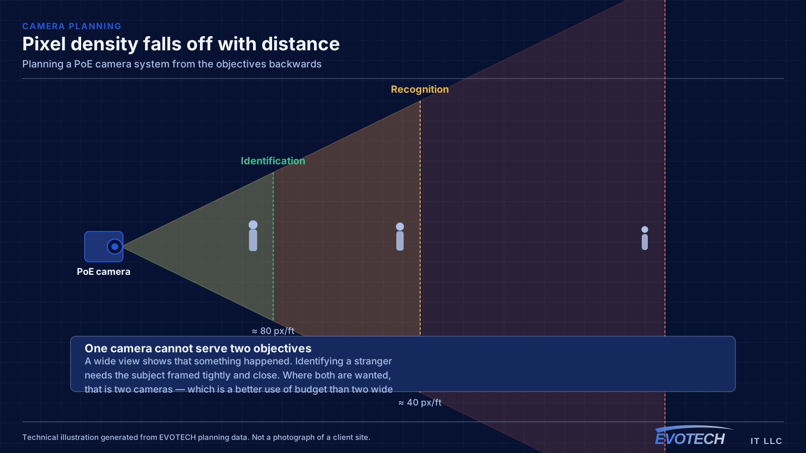
Start by writing down what each camera has to accomplish. Detecting that activity occurred, recognising someone already known, and identifying a stranger are three different requirements needing progressively more pixel density on the subject. Common planning targets are roughly ten pixels per foot of subject for detection, forty for recognition, and eighty for identification.
That number, combined with the distance to the area being covered, determines the lens and the mounting position. It is why a well-planned four-camera system regularly outperforms a poorly planned twelve-camera one, and why higher resolution alone does not produce usable footage — a high-resolution camera aimed at a wide area spreads its pixels thin.
Writing the objective before choosing the camera
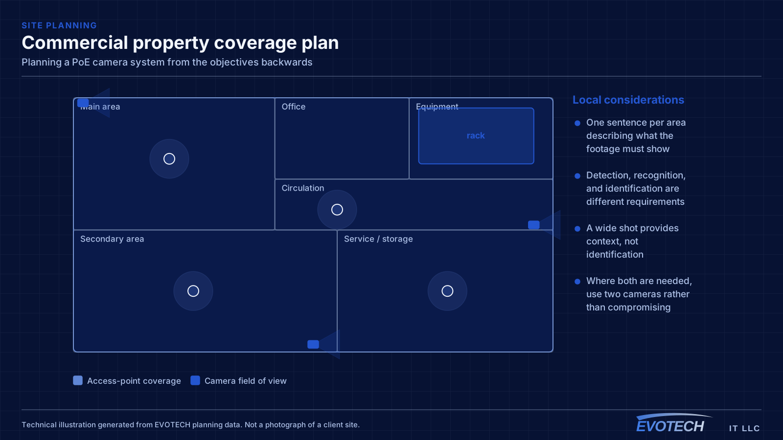
For each area, write one sentence describing what the footage has to show. 'Identify anyone entering through the front door.' 'Show whether the loading bay gate was left open.' 'Show what was handed across the counter.' Those sentences determine everything downstream.
The common failure is an unstated objective, which defaults to 'see the area' — and a camera that sees an area satisfies nobody when something happens in it. The wide shot has genuine value for context; it just cannot also be the identification camera.
Where both are needed, that means two cameras: one framed tightly on the approach for identification, one wide for context. That is a better use of budget than two wide cameras, and it is a conversation worth having before hardware is chosen.
- One sentence per area describing what the footage must show
- Detection, recognition, and identification are different requirements
- A wide shot provides context, not identification
- Where both are needed, use two cameras rather than compromising
- Objectives determine lens and mounting distance
Lighting decides more than the sensor does
Two lighting situations account for most disappointing footage. The first is backlighting: a camera pointed at a glazed entrance or toward the sky during daylight sees a bright background and a dark subject. Wide dynamic range helps, but repositioning so the camera is not metering against a bright source helps far more and costs nothing.
The second is infrared reflection at night. Integrated illuminators work well over modest distances and reflect badly off nearby surfaces — a camera tucked under a soffit with a wall a foot away illuminates the wall and washes out the scene. Mounting clear of adjacent surfaces, or using separate illumination positioned away from the lens, resolves it.
Where usable colour footage at night matters — vehicle colour, clothing colour — that is a lighting decision rather than a camera decision. Ambient white light in the scene produces colour footage; infrared produces monochrome regardless of the camera.
- Avoid metering against glazing, sky, or fixed light sources
- Keep infrared illumination clear of nearby soffits, eaves, and walls
- Separate illumination positioned away from the lens where needed
- Colour at night requires ambient white light, not infrared
- Verify against recorded footage after dark, not a live daytime view
The PoE budget, calculated before ordering
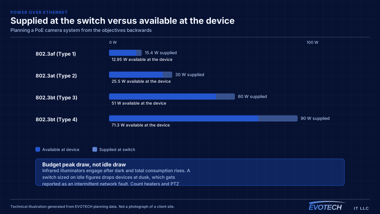
PoE classes escalate: Type 1 supplies up to about 15.4 W at the switch, Type 2 up to about 30 W, and Type 3 and Type 4 under the later standard reach roughly 60 W and 90 W. Available power at the device is always less than supplied, and the gap grows with cable length.
Budget from peak draw with illuminators, heaters, and motors active — not idle draw. This is the specific arithmetic error that produces cameras rebooting after dark, because that is exactly when the additional load arrives. Pan-tilt-zoom cameras and heated housings belong in the calculation individually rather than averaged in.
Then leave headroom. A switch running at its budget has no room for the camera added next year, and adding one at that point produces intermittent faults across the whole system rather than a clear failure on the new device.
- Budget peak draw, not idle draw
- Count illuminators, heaters, and PTZ motors individually
- Available power at the device is less than supplied at the switch
- Leave headroom for future additions
- Put the switch on a UPS so brief outages do not create gaps
Storage sized to a retention target that means something
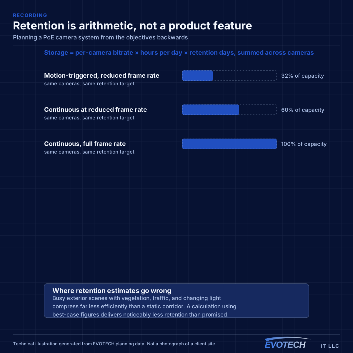
Retention is arithmetic: per-camera bitrate multiplied by hours recorded per day multiplied by retention days, summed across cameras. The variables that move it most are resolution, frame rate, and recording mode.
The estimate goes wrong when it uses best-case compression figures. Busy exterior scenes with vegetation, traffic, and changing light compress far less efficiently than a static corridor, and a system sized on optimistic figures delivers substantially less retention than promised.
Recording mode is the biggest single lever. Continuous recording captures everything and consumes the most. Motion-triggered consumes far less and depends on detection working reliably, which outdoor scenes make difficult. A common middle path records continuously at a reduced frame rate and raises it on motion.
- Storage = bitrate × hours per day × retention days, summed
- Use realistic bitrates for the actual scenes, not best case
- Recording mode dominates the total requirement
- Drives suited to a continuous-write workload
- Verify real consumption over several days after installation
Position, mounting, and verification
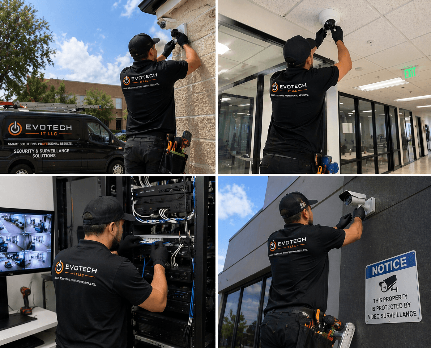
Mounting height involves a genuine trade. High mounting protects the camera and widens the view, and it steepens the angle — a steep downward view mostly records the tops of heads. For identification, mounting nearer face height along the approach path produces far better footage, accepting a more reachable camera and a housing appropriate to that.
Exterior mounting in a humid climate needs housings genuinely rated for driven rain and every penetration sealed with a drip loop. The typical failure is internal condensation producing a hazy image rather than an obvious break, which means it goes unnoticed for a while.
Verification happens against recorded footage in real conditions — daylight at the entrance, after dark at the perimeter — before the system is signed off. A live view on a monitor during commissioning at midday proves very little about what the recording will show at nine in the evening.
- Balance mounting height against viewing angle for identification views
- Housings rated for driven rain, penetrations sealed with drip loops
- Review recorded footage in daylight and after dark before sign-off
- Confirm no unintended blind spots at frame edges
- Configure remote access deliberately, with per-user permissions
The gaps a camera plan usually leaves
Three areas get missed with enough regularity to be worth naming explicitly.
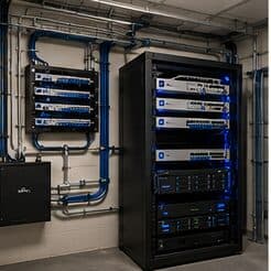
The first is the equipment room itself. A recorder holding every camera's footage sits in a room that frequently has no coverage and, in many installations, no access control either. Anyone reaching the recorder can end the investigation before it starts, which makes the equipment room one of the more sensible places for a camera and a door record.
The second is the transition zones — the corridor between a covered entrance and a covered interior, or the stretch of yard between a gate camera and a building camera. Coverage designed area by area tends to leave someone appearing at one camera and reappearing at another with no continuity between them, which makes footage much harder to interpret.
The third is what happens at the edges of frame. A camera framed on a doorway often has usable footage only in the centre of its view, with the edges too oblique or too distant to be useful. Confirming the actual usable area, rather than the nominal field of view, is what stops two adjacent cameras from leaving a gap between them.
- The equipment room holding the recorder, which is rarely covered
- Transition zones between covered areas, which break continuity
- The usable portion of each frame, which is smaller than the nominal view
- Approaches from directions nobody expects people to arrive from
- The period between an incident and someone noticing it, which sets retention
Frequently asked questions
How many cameras does a site need?
Count objectives rather than walls. Each area needs a stated purpose, and the camera serving it is chosen for that purpose. A site with four well-framed cameras at the points that matter usually produces more useful footage than one with twelve wide views covering everything approximately.
Does higher resolution solve poor footage?
Only if the problem is pixel density and the framing is already right. A high-resolution camera aimed at a wide area still spreads its pixels thin across the scene, so the subject gains little. Framing tighter on a smaller area usually improves identification more than increasing resolution on the same wide view.
Why do cameras drop off the network after dark?
Almost always the PoE budget. Infrared illuminators engage at dusk and total draw rises past what the switch can supply, so devices reboot. It presents as an intermittent network fault and gets diagnosed as one. Budgeting from peak draw with headroom prevents it entirely.
How long should footage be retained?
Long enough that an incident is still on disk when someone notices it. Two weeks is a common baseline and thirty days a frequent business requirement. Whatever the target, verify it against measured consumption after a week of real recording rather than trusting the initial calculation.