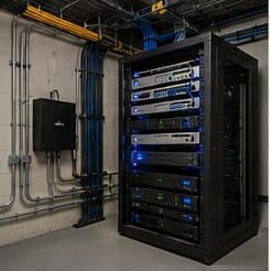

The short answer
Telecommunications grounding and bonding under ANSI/TIA-607 builds a continuous, low-impedance path from every rack and cable pathway back to the building's electrical service ground. It starts at the Telecommunications Main Grounding Busbar (TMGB), a pre-drilled copper busbar (typically 6 mm thick, 100 mm wide, length as needed) mounted near the service entrance and bonded to the building electrical grounding system. From the TMGB, an insulated Telecommunications Bonding Backbone (TBB) runs vertically through the building to a Telecommunications Grounding Busbar (TGB) in each telecom room. Racks, ladder rack, cable tray, and equipment then bond to the nearest TGB. The TBB minimum is #6 AWG, sized up with backbone length; the conductor to a TGB is commonly #6 AWG minimum. Everything shares one reference so no two chassis sit at different potentials.
The reason this matters for AV and networking is the ground loop. When two pieces of connected gear are grounded at points sitting at slightly different voltages, current flows through the signal cable's shield or ground, and on analog audio/video you hear it as 60 Hz hum or see it as rolling hum bars. Single-point, or star, grounding, where every ground path converges at one busbar rather than forming a closed loop, is the structural fix. On shielded runs, terminating the cable shield at one end only prevents the shield from becoming a second ground path. Isolated grounding, surge protection, and proper lightning/entrance protection where cable enters the building complete the system. Done correctly, grounding is invisible; done poorly, it shows up as noise, data errors, and failed gear.
What to Get Right Before Anything Else
Grounding and bonding are two different jobs that people blur together. Grounding connects a system to earth, establishing a zero-voltage reference. Bonding connects metallic parts to each other so they share the same potential and any fault current has a low-impedance path back to the source. ANSI/TIA-607 (aligned internationally with ISO/IEC 30129) governs the telecommunications-specific version of both. It does not replace the electrical grounding required by the National Electrical Code (NFPA 70); it ties into it. The telecommunications grounding system bonds to the building's electrical grounding electrode system, never to a separate, independent ground rod. Two isolated ground fields at different potentials are exactly what creates the hazards and noise TIA-607 exists to prevent.
The decision that shapes an install is topology: everything must trace back to a single reference point. That is the single-point or star principle. The TMGB is that point for the building; each TGB is the local star for its telecom room. Racks and pathways bond outward from the TGB in a tree, never in a ring. The moment two ground paths close into a loop, you have created the mechanism for circulating current. For AV in particular, where analog audio and unbalanced video are sensitive to millivolt-level differences, this single decision determines whether the system is quiet or hums.
The second decision is conductor sizing, which is driven by backbone length, not guesswork. The TBB grows in cross-section as it gets longer to keep impedance low, and the standard publishes a length-to-size table. Undersizing the backbone defeats the whole system because a high-impedance ground is barely a ground at all during a surge or fault. Get topology and sizing right and the rest is workmanship.
- ANSI/TIA-607 covers telecommunications bonding and grounding; it supplements, not replaces, NEC (NFPA 70) electrical grounding.
- Grounding = connection to earth reference; bonding = connecting metal parts so they share one potential and carry fault current.
- Bond the telecom grounding system to the building's electrical grounding electrode system; never install a separate isolated telecom ground rod.
- Topology is single-point/star: TMGB is the building reference, each TGB the room reference; branches radiate outward, never form a ring.
- TBB conductor size scales with backbone length per the published table; a high-impedance ground fails during surge and fault events.
The TMGB, TGB, and TBB Hierarchy
The Telecommunications Main Grounding Busbar (TMGB) is the origin of the telecommunications grounding system. It is a predrilled, electro-tin-plated (or bare) copper busbar, commonly 6 mm (1/4 in) thick and 100 mm (4 in) wide, with length chosen to fit the number of connections. It sits near the service entrance or main telecom space and is bonded to the building electrical grounding system with a bonding conductor sized no smaller than the largest TBB it serves. The TMGB is the physical embodiment of the single-point principle for the whole structure: every telecommunications grounding path in the building ultimately terminates here.
From the TMGB, one or more Telecommunications Bonding Backbones (TBB) run through the building, typically riser to riser, connecting the TMGB to a Telecommunications Grounding Busbar (TGB) in each telecom room, equipment room, or entrance facility. The TBB is an insulated copper conductor; where multiple TBBs exist in a multistory building, they are joined at the top and at least every third floor by a Grounding Equalizer (GE, sometimes TBBIBC) to keep vertical busbars at equal potential. The TGB is a smaller copper busbar serving its local room, and everything in that room, racks, cable tray, ladder rack, metallic conduit, and equipment, bonds to it.
This produces a clean tree: equipment to TGB, TGB to TBB, TBB to TMGB, TMGB to building electrical ground. Each junction is a mechanical, low-impedance connection using listed two-hole lugs, antioxidant compound on the contact surface, and torqued hardware. Because the structure is a tree and not a mesh, no closed loop forms, and fault or surge current has exactly one intended path to follow.
- TMGB: copper busbar commonly 6 mm (1/4 in) thick and 100 mm (4 in) wide, predrilled, near the service entrance; the building's single grounding origin.
- TGB: smaller copper busbar in each telecom/equipment room; local star point for racks, tray, conduit, and gear.
- TBB: insulated copper conductor from TMGB to each TGB; minimum #6 AWG, sized larger by length.
- Grounding Equalizer (GE): bonds multiple TBBs together at the top floor and at least every third floor in multistory buildings to equalize vertical potential.
- Connections use listed two-hole compression lugs with antioxidant compound and specified torque; bond every rack and pathway to the nearest TGB.
Conductor Sizing by Length
The TBB is sized by its length because conductor impedance rises with distance, and a grounding conductor is only useful if it stays low-impedance. ANSI/TIA-607 publishes a length-to-size table. As a working reference, a TBB up to about 4 m (13 ft) uses #6 AWG; up to about 6 m (20 ft), #4 AWG; up to about 8 m (26 ft), #3 AWG; up to about 10 m (33 ft), #2 AWG; up to about 13 m (43 ft), #1 AWG; up to about 16 m (52 ft), #1/0; up to about 20 m (66 ft), #2/0; and beyond roughly 20 m, #3/0 or larger. The exact breakpoints come from the current edition of the standard; the principle is fixed: longer backbone, larger conductor.
The bonding conductor from a TGB, and from equipment to a TGB, is commonly #6 AWG copper as a practical minimum, scaled up where distance or the served load warrants. The bonding conductor between the TMGB and the building electrical grounding system is sized no smaller than the largest TBB connected to that TMGB. All telecommunications bonding conductors are copper; TIA-607 does not permit aluminum for these paths. Conductors should be continuous where practical, routed as straight and short as the space allows because sharp bends and excess length add impedance that matters during fast surge transients.
Rack bonding uses a dedicated rack grounding busbar or a listed rack-bonding kit rather than relying on painted rack-frame joints, which are not a reliable electrical path. Each rack unit's bonding jumper lands on the rack busbar, and the rack busbar bonds to the TGB. Paint under lugs is removed or paint-piercing washers are used so metal contacts metal.
- TBB by length (reference, per TIA-607 table): up to 4 m #6 AWG; 6 m #4; 8 m #3; 10 m #2; 13 m #1; 16 m #1/0; 20 m #2/0; beyond ~20 m #3/0+.
- TGB and equipment bonding conductors: commonly #6 AWG copper minimum, sized up with distance and served load.
- TMGB-to-electrical-ground bonding conductor: no smaller than the largest TBB served by that TMGB.
- All telecommunications bonding conductors are copper; aluminum is not used for these paths.
- Keep grounding conductors continuous, short, and gently routed; sharp bends and excess length raise impedance during surge transients.
- Bond racks with a rack grounding busbar or listed kit; pierce or remove paint so lugs make metal-to-metal contact.
Ground Loops, Shields, and Isolated Grounds
A ground loop forms when a signal cable connects two devices that are each grounded, and those two ground points sit at slightly different voltages. That small potential difference drives a current around the loop formed by the signal path and the ground paths. In balanced digital links the effect is usually rejected, but in analog audio it becomes audible 60 Hz hum and its harmonics, and in unbalanced or composite video it appears as slowly rolling horizontal hum bars. The mechanism is real electrical current, not interference picked from the air, which is why software or cable swaps rarely fix it. The cure is structural: give everything one ground reference so there is no potential difference to drive a loop, which is exactly what single-point grounding to a common TGB achieves.
On shielded cable runs, the shield should generally be terminated at one end only. If the shield is bonded to ground at both ends and those grounds differ in potential, the shield itself becomes a second conductor carrying loop current, which then couples noise into the signal it was meant to protect. Grounding one end lets the shield drain interference to ground while breaking the loop. The correct end depends on the signal standard and system design, so it is decided deliberately, not left to chance.
Isolated grounding (IG) receptacles, the orange-triangle outlets, carry an insulated equipment ground back to a single point to keep noisy branch-circuit grounds off sensitive equipment. They must still bond to the same building grounding system, just via a controlled path, or they reintroduce the two-potential problem. Transformer-based isolation and balanced interconnects address stubborn cases without defeating safety grounding.
- Ground loop mechanism: two grounded, interconnected devices at different ground potentials drive circulating current through the signal/shield path.
- Symptoms: 60 Hz hum plus harmonics in analog audio; rolling horizontal hum bars in unbalanced/composite video; possible data errors on marginal links.
- Structural fix: single-point/star grounding to a common TGB removes the potential difference that drives the loop.
- Shielded runs: terminate the shield at one end only so it drains noise without becoming a second ground-current path; the chosen end follows the signal standard.
- Isolated-ground (IG) receptacles route an insulated equipment ground to a single point but must still bond to the building grounding system.
- Never lift a safety ground to silence hum; use single-point bonding, one-end shields, balanced/isolation interfaces instead.
Surge, Lightning, and Entrance Protection
Where copper cabling enters a building from outside, whether an inter-building fiber's metallic strength member, a coax run, or a copper telecom feed, the entrance is the point of highest surge and lightning exposure. TIA-607 and NEC Article 800/770/820 require that these entrances be protected and bonded to the grounding system close to where the cable enters. A primary protector (a listed surge/lightning protector) on outside-plant copper diverts transient energy to ground before it reaches equipment. The protector ground bonds to the TMGB or a nearby bonded busbar with a short, direct conductor, because a long or coiled ground lead adds impedance that lets dangerous voltage develop during a fast strike.
Surge protective devices (SPDs) provide layered defense: entrance-level protection at the service, then equipment-level protection at racks and sensitive gear. They shunt overvoltage to the grounding system, so their effectiveness is entirely dependent on a low-impedance bond back to the same single-point reference. An SPD tied to a poor ground is little better than none. For AV and network racks, PDUs with integrated SPD and proper rack bonding cover the equipment layer.
Outdoor devices, PTZ cameras, gate controllers, parking-lot access points, and antennas need their own bonding and surge protection at the structure, and metallic pathways between buildings must be bonded at both structures per code. Lightning protection system (LPS) down-conductors and the telecommunications grounding system are bonded together at the common grounding point so a strike cannot split into two potentials. The recurring theme is that every protective device is only as good as the single, low-impedance ground it discharges into.
- Protect and bond every outside-plant copper entrance (coax, copper telecom, metallic strength members) close to the point of entry; governed by NEC Articles 800/770/820.
- Use a listed primary protector on outside copper to divert lightning/surge energy to ground before it reaches equipment.
- Keep protector and SPD ground leads short and direct; long or coiled leads add impedance and let dangerous voltage build during fast transients.
- Layer surge protection: entrance-level SPD at the service, equipment-level SPD at racks and sensitive gear (including rack PDUs with SPD).
- Bond outdoor devices (PTZ cameras, access points, antennas, gate controllers) locally and protect them at the structure.
- Bond the lightning protection system and the telecommunications grounding system to the common grounding point so a strike cannot create two potentials.
Frequently asked questions
What is the difference between grounding and bonding?
Grounding connects a system to earth to establish a zero-voltage reference. Bonding connects metallic parts to each other so they share the same electrical potential and any fault current has a low-impedance path back to the source. TIA-607 requires both: equipment and pathways are bonded together, and that bonded system is grounded to the building's electrical grounding electrode system. They work together; one without the other leaves either a floating reference or unequal potentials between chassis.
What size conductor does TIA-607 require for the bonding backbone?
The Telecommunications Bonding Backbone (TBB) is sized by its length using the table in ANSI/TIA-607. As a reference, up to about 4 m uses #6 AWG, up to 6 m #4 AWG, up to 8 m #3 AWG, up to 10 m #2 AWG, up to 13 m #1 AWG, up to 16 m #1/0, and up to 20 m #2/0, going larger beyond that. All telecommunications bonding conductors are copper. Longer runs need larger conductors to keep impedance low during surge and fault conditions.
Why does my AV system hum, and does grounding fix it?
A steady 60 Hz hum in audio, or rolling hum bars in video, usually comes from a ground loop: two interconnected devices grounded at points sitting at slightly different voltages, which drives circulating current through the cable shield or signal ground. The fix is structural, not a filter or cable swap. Single-point (star) grounding, where everything references one common busbar, removes the potential difference. Terminating shields at one end only and using balanced or transformer-isolated interfaces address stubborn cases. Never lift a safety ground to silence hum.
Should cable shields be grounded at one end or both ends?
On most shielded runs the shield is terminated at one end only. If it is grounded at both ends and those grounds differ in potential, the shield itself becomes a second conductor carrying loop current and couples noise into the signal. Grounding one end lets the shield drain interference to ground while breaking the loop. Which end is grounded depends on the signal standard and system design, so it is chosen deliberately as part of the install, not left to whichever connector happens to make contact.
Does TIA-607 grounding replace NEC electrical grounding?
No. ANSI/TIA-607 is the telecommunications-specific bonding and grounding standard, and it supplements the electrical grounding required by the National Electrical Code (NFPA 70). The telecommunications grounding system bonds to the building's existing electrical grounding electrode system; it never uses a separate, independent ground rod. Installing an isolated telecom ground would create two ground fields at different potentials, which is exactly the hazard and noise source both standards exist to prevent.